
The Hidden Edge of Streamlining
In a previous post, I mentioned that “Air molecules do not like to turn corner.” Let’s dive deeper into how drag is created and what we can do to reduce it.
Understanding the Source of Drag
Air molecules like to go straight. Whenever an object is in the way, the air has to turn. From the perspective of the moving object, it must constantly push the air molecules out of its path. This results in a resistance or opposing force.
This resistance, or drag, either slows the object down or requires the object to generate a force (thrust) to maintain its speed. When the speed is constant, the required thrust exactly equals the drag (Newton’s third law). This air resistance is the fundamental source of drag.
Minimizing Resistance with Streamlining
What kinds of shapes move through the air with the least resistance?
Generally speaking, a smooth object with a smaller frontal area experiences less drag. When comparing objects with the same frontal area but different shapes, the tear-shaped or “streamlined” object is the clear winner. (See a comparison below.)
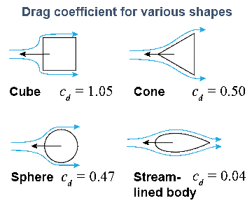
Shapes with smaller drag coefficients are more aerodynamic. Ref: https://fsacta.weebly.com/drag.html
Since modern airplanes and race cars need to move through the air with minimal effort, almost all aspects of them are highly streamlined. Engineers spend countless hours in wind tunnels and on computers to perfect these designs. We can examine any of them to learn the art and science of streamlining, and apply it to make our aircraft fly better.
See below. This solar car is an excellent streamlining example. It achieves highway speeds using power equal to a home hair dryer – an astonishing level of efficiency! The CarSol Zephyr solar car won many trophies, including the championship title at the 2017 Formula Sun Grand Prix in Austin, TX!

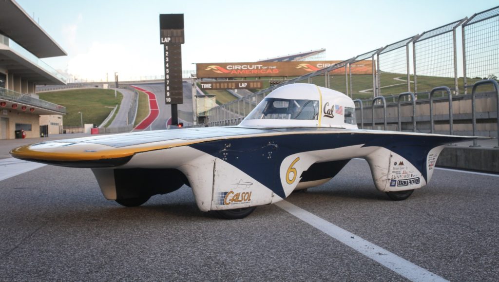
CalSol – The UC Berkeley Solar Vehicle Team
Design Features that Reduce Drag
To illustrate this streamlining principle, let’s highlight a few examples you can apply to your own designs:
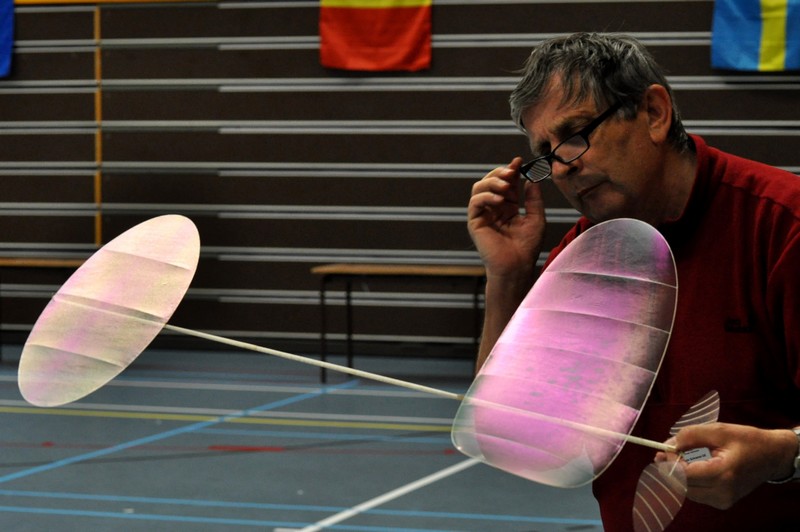
- Rounded Wingtips: Notice the smoothly rounded corners on many modern airplane wingtips, especially on the leading edge (e.g., F1D winning model aircraft).
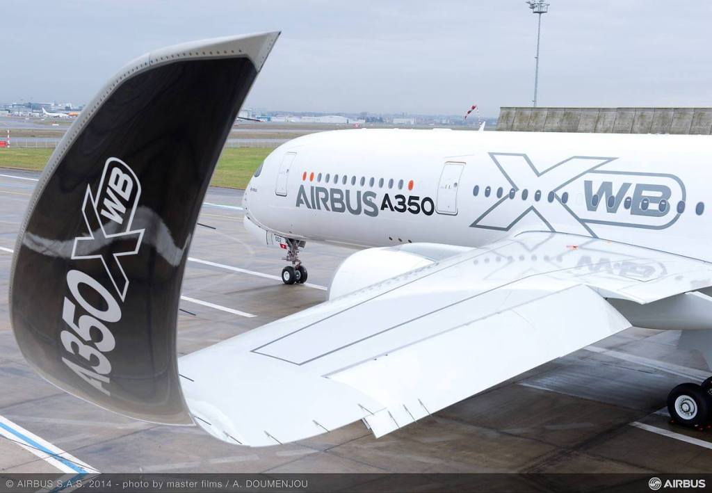
- Seamless Winglet Transitions: Look at the seamless transition of modern winglets (e.g., Airbus A350). (For an alternative, note that the engineers of the Boeing 787 Dreamliner utilize smoothly extended raked wingtips, opting for no winglets, for even better drag reduction.)
- Filleted Joints: You will not see any perpendicular intersections of two surfaces on a streamlined modern aircraft. Good examples include the wing-to-fuselage joints on many jets, like the F-16, and even World War II fighters, like the famous Spitfire. The curved transition (fillet) keeps the airflow smooth. (See photos below.)


Applying Streamlining to SO Aircraft
Hopefully, you now understand the reasons behind many features of successful Science Olympiad airplanes and helicopters.
Take my Apache24s airplane as an example; it has no right-angle wingtip plate on the main wing. No interference drag. To further minimize drag, the wingtips are also rounded.
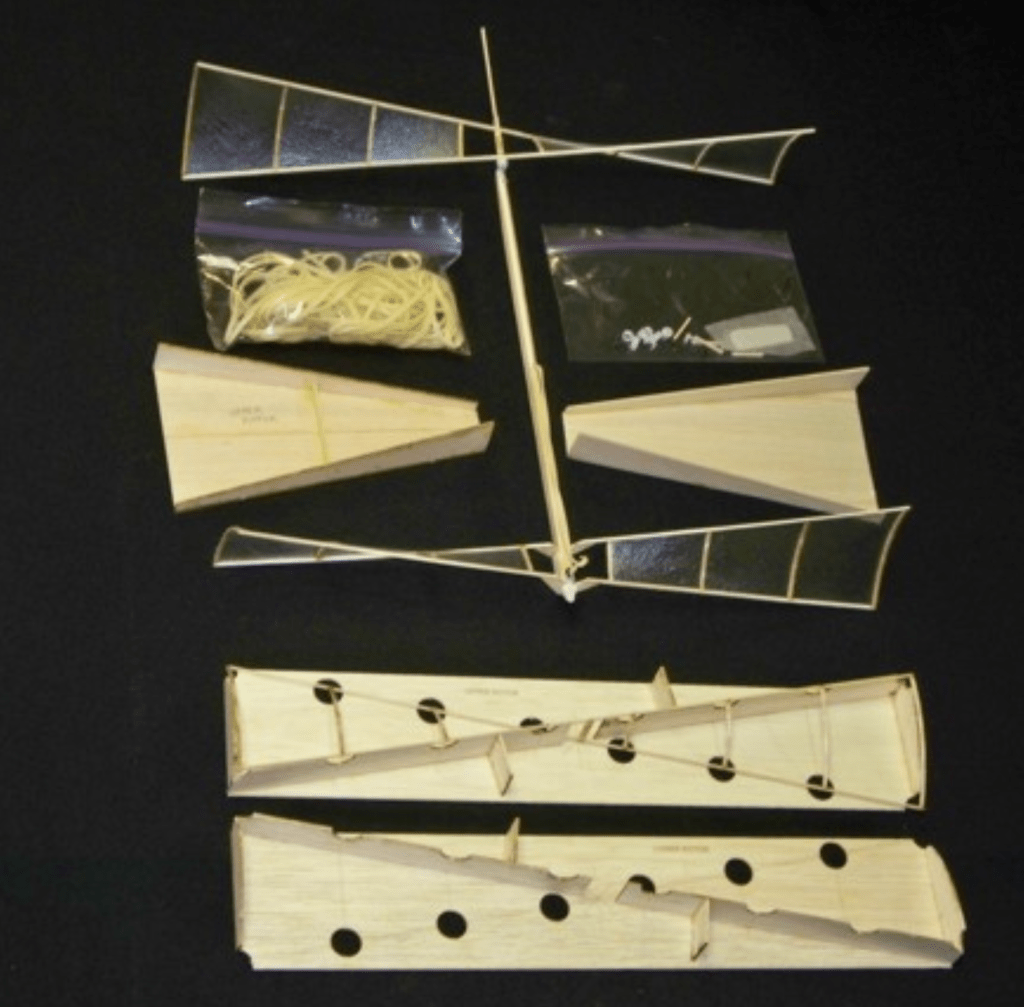
Here is a sharp-corner example. Traditional SO helicopters often use straight-edged (X-style) rotor blades, where the sharp-cornered blade tips look inefficient. No full-scale helicopter uses this type of blade. (See samples below.)

As a counterexample, the 2025 National Division C Champion helicopter is equipped with two “fishbone” rotors that have no sharp corners at the blade tips. (See photos below.) This fishbone rotor is much like a modern streamlined propeller. On the 2025 champion helicopter, the two fishbone rotors alone were responsible for extending its already excellent three-minute flight time by nearly one full minute!
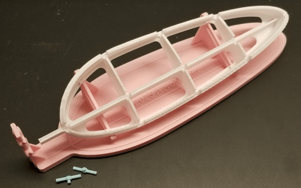
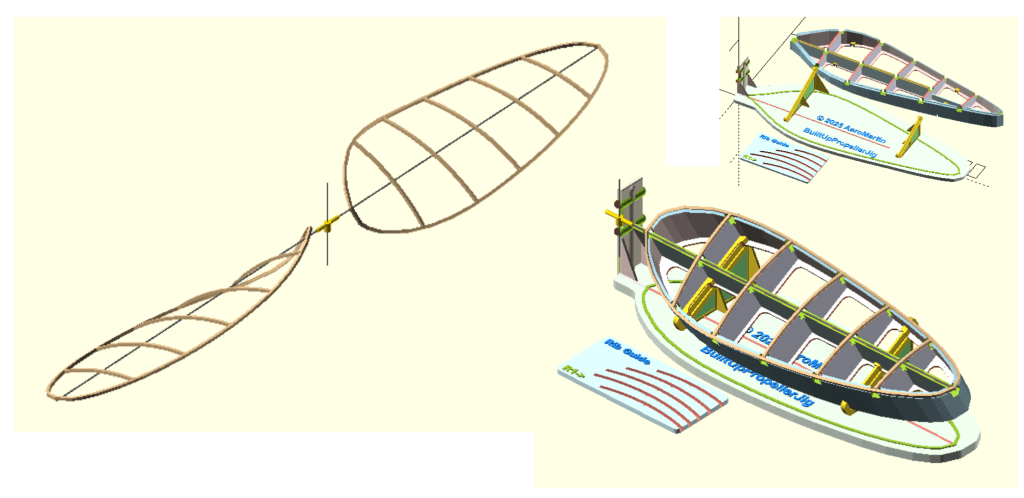
The fishbone blade design also incorporates other features to further reduce drag, such as an improved blade chord distribution. We can discuss this and other features in future notes.
Hope this write-up helps you build a better SO aircraft and improve your next innovative SO design. Feel free to comment below or drop me an email if there are other topics or features you would like to discuss.
Aim high and fly high!
-AeroMartin 11/08/2025

Leave a reply to AeroMartin Cancel reply