
In this write-up, I treat “propeller” and “rotor” as the same device that accelerates air. When necessary, I will add “airplane” or “helicopter” in front of them, respectively, to distinguish the two.
What is Pitch?
Propeller Pitch is the theoretical distance a propeller would move forward in one complete revolution.
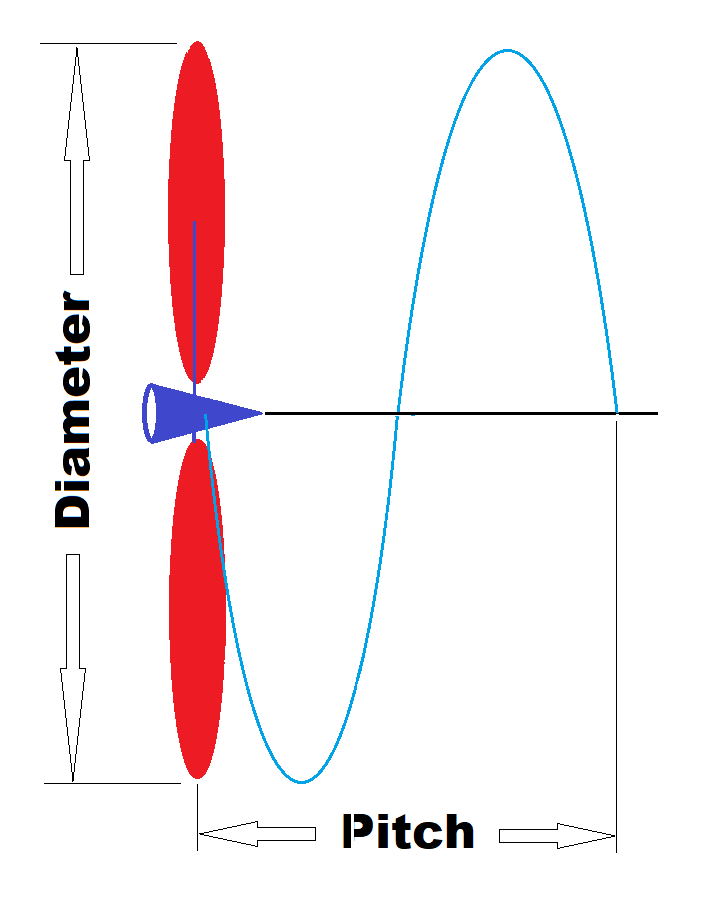
Picture 1: Pitch definition
However, all points on a blade may not move forward the same distance after one revolution. This raises the question: Which point on the blade should we measure the pitch? For many free flight propellers, the pitch is usually measured at 75% of the blade’s radius. Since it is easier to measure the angle than the distance it travels, we normally specify the “Pitch Angle” at this 75% radius instead of the “Pitch” (distance) of a propeller.
My two flexible pitch gauges are designed to measure pitch angle at the 75% radius location of a propeller/rotor. FYI.

Picture 2: Pitch Angle at 75% radius.
What is Helical Pitch?
When a propeller blade is designed so that all points on the blade travel the same distance forward per revolution, this blade is said to have helical pitch or helical pitch distribution, also known as helix pitch in many places.

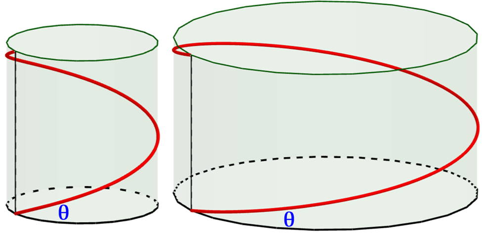
Picture 3: Left: Pitch angle near the root, Right: Pitch angle at the blade tip. For a helical propeller, all points on the blade advanced to the same distance.
Problems with a Constant Angle Blade
When a helicopter utilizes a constant pitch angle along the entire blade (usually with a constant chord length, too.) What problems does this cause?
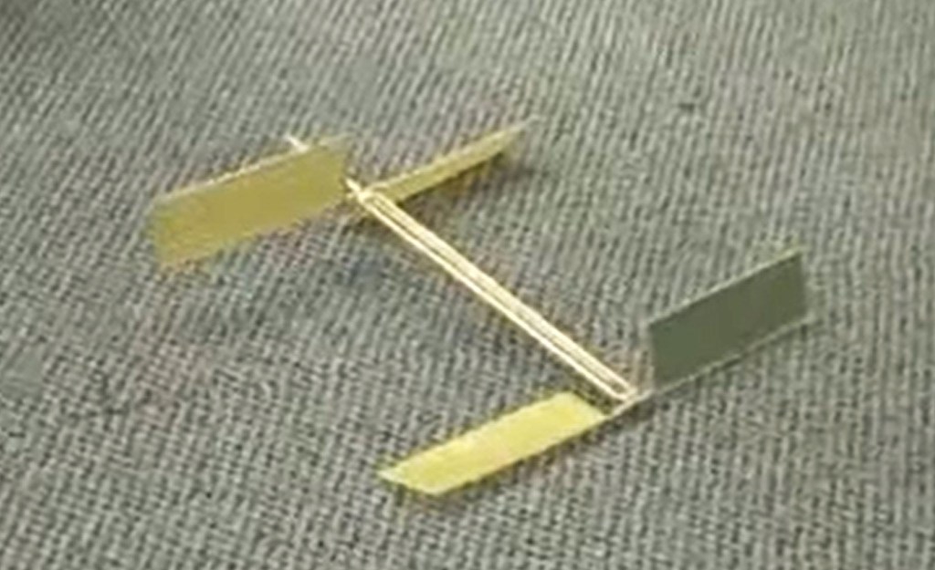
Picture 4: constant pitch angle, constant chord, blades
A propeller blade is essentially a rotating wing, and its efficiency relies on maintaining an optimal Angle of Attack (AOA) with the incoming air (relative airflow). However, the speed of the blade varies greatly from the root to the tip; the tip travels much faster than the area near the hub.
If a propeller has the same blade angle along its entire length, like some toy helicopters, the following problems occur:
- Near the hub: The blade section moves too slowly, potentially resulting in a negative AOA and little to no thrust.
- Since this root portion of a blade is moving at a very slow speed, little to no thrust can be harvested. For my Apache23 airplane propeller, as well as my Viper25 helicopter rotor, I purposely cut off this root portion to avoid any drag this portion generates.
- At the tip: The blade section at the tip moves too fast for its angle, leading to an AOA that is too high, causing stall conditions and creating significant drag.
- This excessive drag requires a greater torque to overcome and turn the blade.
- This also means the blade needs extra structural strength to deliver the torque. And, extra structural strength means unnecessary weight! Not ideal!
Is a Helical Blade the Best Design?
Let’s define “the best” first. In SO competition, flying for the longest time is the goal, which means we want our propellers/rotors to have the best Lift over Drag (L/D) ratio. (We will discuss this in detail in a future note.)
For a section of the blade to have the best L/D ratio, there is a certain AOA to aim for. When all sections on the blade are at their best AOA, the whole blade will achieve its best L/D ratio.
Note that we do not have direct control of AOA. We approach the best blade by designing and varying the rotor’s pitch angle at each section. When designed properly, the blade’s rotational speed and the propeller’s forward/upward speed would then match the optimal AOA.
Under the assumption that the incoming air speed is uniformly constant anywhere on the blade, a helical angle distribution would ideally result in a constant AOA at each and every section. And, if this constant AOA happens to be the optimal AOA, this blade will then be rotating at its best L/D, meaning it is at its best efficiency.
Note the underlined “under the assumption” and “ideally” above. Observe the airflow around a hovering helicopter near the ground below. This is essentially the reversed airflow of a SO helicopter hovering under a ceiling. The incoming airspeed is not uniformly constant.

Picture 5: non-uniform incoming airflow with a hovering helicopter
In short, the engineered helical pitch distribution ensures that the AOA is close to optimal and relatively uniform along the entire span of the blade, maximizing efficiency and minimizing drag. However, since the assumed ideal condition (uniform incoming speed) is not true in reality, this helical twisted blade is NOT the best, but it is close.
Improving a Helical Propeller/Rotor
There are many Computational Fluid Dynamics (CFD) software packages that can simulate and analyze the swirling flow around a propeller/rotor. This helps further alter the helical twist at each section to bring the AOA closer to the optimal, thereby improving the overall propeller’s efficiency. (Note: any simulation has its limitations and will need real-life validation.)
For many real-world airplane propeller applications, since the incoming speed is high and almost uniform, a helical pitch distribution is quite good. On the other hand, many drones or helicopters spend most of their time hovering. In the SO helicopter case, most of its time is spent hovering under a restricted ceiling. The uniform incoming speed assumption that works for airplane propellers is an exaggeration for such a hovering helicopter rotor, especially at the tips.
Picture 6: Propeller Design CFD Simulation
I introduced a washout variable in my two helicopter blade jig programs (as well as my propeller mold program) to help with this. Washout is defined as a decreased pitch angle toward the blade (or wing) tip. Adding washout to a blade is generally a key design feature that helps match the blade’s pitch angle to the non-uniform incoming air speed, which improves the overall propeller/rotor’s propulsive efficiency.
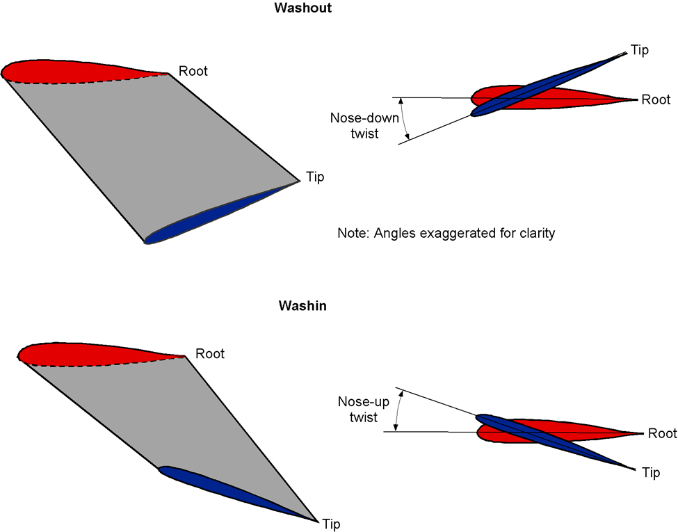
Picture 7: washout vs. washin

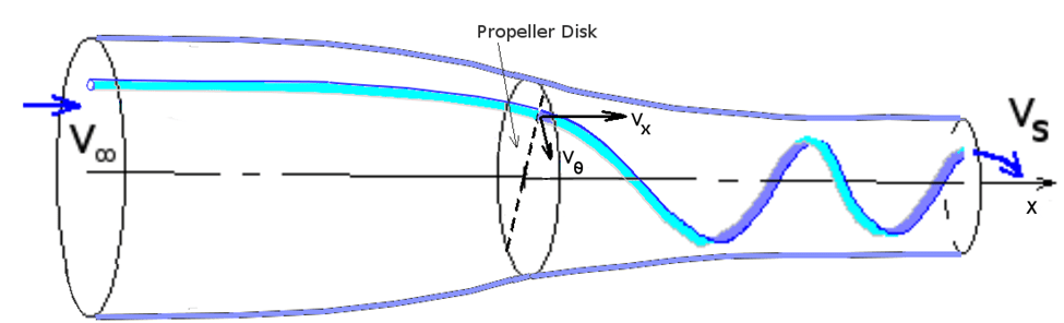
Picture 8: stream tube airflow around a propeller
How Much Washout is Needed?
Well, that is another million-dollar question. Like what is the best pitch (as outlined in my “Pitch Perfect“), the answers require experiments to determine. Each application has its unique considerations.
- A helical propeller without washout may be good enough for an airplane.
- A rotor with helical twist plus a few degrees of washout might be better for hovering drones and helicopters. Do not use excessive washout. Too much washout can result in a negative AOA at the blade tip, resulting in an undesirable and unusual behavior of reverse thrust, intermittently. It is funny to watch, though! 🙂
Knowing that a few degrees of washout could help, plus the understanding of “Pitch Perfect,” will help you experiment and come up with the perfect rotor blade design! It is a competition. The more experiments you conduct, the better chance you have for finding the best combination of all variables. (See “Optimization Essential” post.)
Feel free to make comments below or contact me directly. Happy to help! Good luck!
-AeroMartin 11/15/2025
P.S. Homework: Use below drawing and the definition of tan(), find the formula to convert Pitch Angle(B) to Pitch(Lead of Helix) on a propeller.
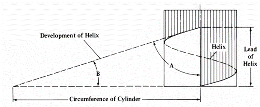
Picture 9: relationship between Pitch Angle and Pitch

Leave a comment